kjen.dk
open source
For a project at the university I needed an antenna signal splitter to share the signal from a single GPS antenna between up to three GPS receivers. I found a few commercial products available but decided it would be much more fun and learning to build it myself.
Design goals
My design goals were:
- Input from one GPS antenna
- Output to three GPS receivers
- DC supply from one (and only one) of the GPS receivers to the GPS antenna.
- Low attenuation
- Low cost
- Simple design
Challenges
There are some challenges building an antenna signal splitter for GPS receivers:
- The GPS signals L1 (1575.42 Mhz) and L2 (1227.60 MHz)1) require the leads between the antenna sockets to be as short as possible to avoid loss caused by self induction of the leads.
- An external GPS antenna typically contains a signal amplifier which is powered by a DC voltage through the antenna cable. When splitting the antenna signal between GPS receivers DC voltage should therefore be blocked to and from all of them except one of the GPS receivers.
Information sources
While googling for similar projects I came across a homebrew splitter design 2) which I have based my design upon. I also got some knowledge and inspiration from 3) 4).
DC voltage blocking
To block the DC voltage to and from all but one of the GPS receiver outputs, capacitors are inserted in series with the center conductor of the transmission line for each of those outputs. Ideally the capacitor shall block any DC voltage and behave as a short at the L1 and L2 frequencies.
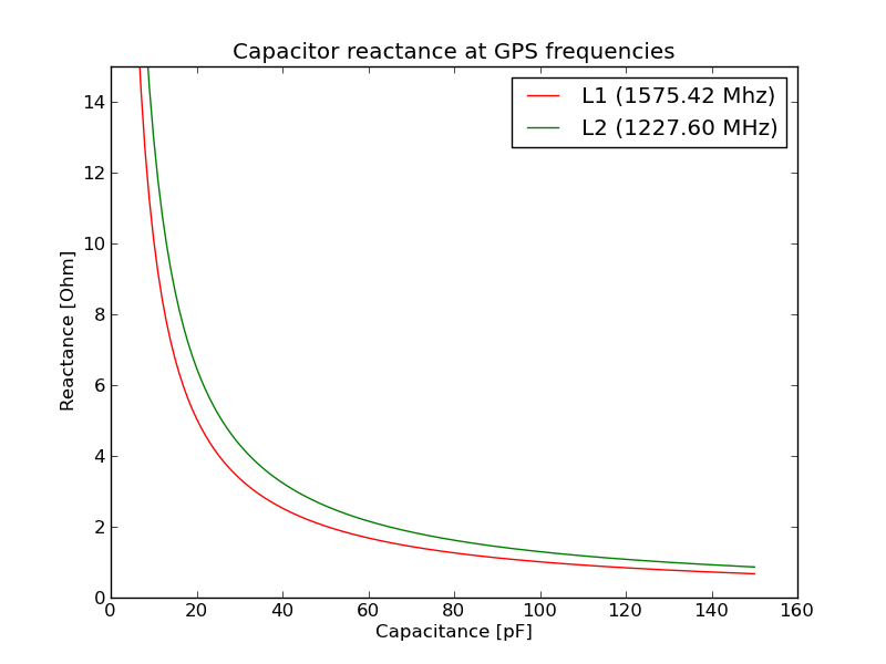
The reactance 5) of a capacitor is given by:
$ X_c = \frac{1}{2 \pi f C}$
Where f is the frequency in Hz and C is the capacitance in Farad. Below is a plot of the reactance at the L1 and L2 frequencies for capacitance between 1 and 150 pF (Python code):
In the real world capacitors are not ideal however, the construction and external leads add inductive and resistive components. This causes a number of complications, one of them being that capacitors have a series self-resonant frequency (SRF) due to parasitic inductance6).
- At frequencies below the SRF the impedance is primarily capacitive.
- At the SRF the capacitive and inductive components cancels each other leaving only the resistive component which is typically stated in the data sheets as Equivalent Series Resistor (ESR).
- Above SRF the impedance is primarily inductive.
In theory the lowest resistance at a working frequency would be obtained by selecting a capacitor with a SRF at this frequency. But since capacitor values are not accurate, SRF should be higher than the working frequency to avoid inductive properties.
SRF depends on the capacitor size and type and is stated in the capacitor data sheet. So selecting the capacitor for this project comes down to making sure that SRF is higher than the L1 frequency and the reactance is as low as possible. Anything below 4 Ohm should be acceptable. Looking at some data sheets the reactance should ideally be between 50 and 75 pF.
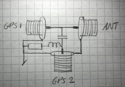
Schematics
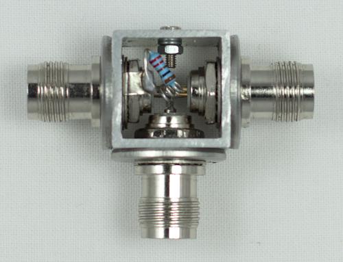
- The GPS1 and Antenna connector are connected directly and the DC supply voltage from GPS1 will therefore reach the antenna.
- The center pin of the GPS2 connector is connected to the center pins of the two other connectors through a capacitor which blocks the DC supply voltage from GPS2.
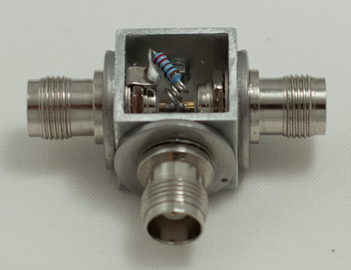
- In order for GPS2 to 'feel' the load of an active antenna, a resistor is connected between the center pin and the shield of the GPS2 connector. The selected resistor is 220 Ohm but the value is not critical.
- To avoid RF voltage across the resistor, one of the legs is coiled up to act as an indoctor. I have no idea of how well this works, but it doesn't hurt.
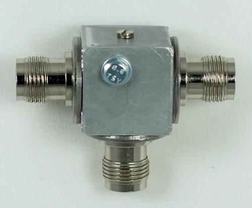
Construction
The construction of the housing is pretty much like 7) but since I chose to use TNC sockets I had to add washers to allow room for all three sockets. the small screw on the fourth side only serves the purpose to close a hole I accidently drilled.
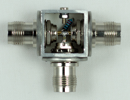

Materials used
- 18 mm of a 20x20x1.5mm aluminium tube
- Three large washers
- Two 20×20 aluminium plates
- 25x3mm bolt and nut
- Three TNC connectors
- Ceramic SMD capacitor 49 pF
- Resistor approx 220 Ohm
Important
- The leads between the TNC connectors including must be as short as possible to avoid losses by self induction.